Showing posts with label intersections. Show all posts

Saturday, November 19, 2011

Linestring/polygon intersection


Linestring/polygon intersection


After a long while a blog again, a short one this time. I'm currently implementing intersections linestring/polygon for Boost.Geometry. Well, the basics (calculating intersection points) are already there for a long time, but for this combination the intersection points should be followed in another way and the correct pieces should be outputted.

When I do these things I normally check the results with both PostGIS and SQL Server. However, I'm encountering something weird in both of them.

The testcase

My testcase is looking like this:


SQL Server

In SQL Server the intersection is correctly done, but the linestring is reversed! I'm using this query:
with viewy as
(
   select
      geometry::STGeomFromText('POLYGON((1 1,1 3,3 3,3 1,1 1))', 0) as p,
      geometry::STGeomFromText('LINESTRING(2 2,1 2,1 3,2 3)', 0) as q
)
select
   p.STIntersection(q).STLength() as len,
   p.STIntersection(q).STAsText() as wkt
from viewy;

and this is my output:

3    LINESTRING (2 3, 1 3, 1 2, 2 2)

You see, the linestring is reversed! It is not only reversed with this linestring, but with all linestrings. Even if they are, for example, complete inside the polygon. If I reverse the polygon (from clockwise to counter clockwise), the output is still reversed. Mysterious...

PostGIS

Also a surprise in PostGIS.The query is looking there as following:

with viewy as
(
   select
      ST_GeomFromText('POLYGON((1 1,1 3,3 3,3 1,1 1))') as p,
      ST_GeomFromText('LINESTRING(2 2,1 2,1 3,2 3)') as q
)
select
   ST_Length(ST_Intersection(p, q)) as len,
   ST_AsText(ST_Intersection(p, q)) as wkt
from
viewy;
and this is here the result:

3;"MULTILINESTRING((1 2,1 3),(1 3,2 3),(2 2,1 2))"

I'm getting a multilinestring back! With respect to contents, it is OK. But it is surprising...

OGC

I did not look it up but I don't think this specific behaviour is specified. So yes, all implementations will be correct but...

Boost.Geometry

At the moment of writing, technically more difficult cases as this is one are not completely finished. But I can already tell that the linestring will not be reversed and that the output will consist of only one linestring...


Sunday, February 13, 2011

Spikes: research with ESRI


Spikes: research with ESRI


A short follow-up on my previous blog about spikes and their causes. My collegue Bert recoded the scenario in C# using ESRI. Thanks Bert! The full code is shown below.

The answer is this: with ESRI the spikes are not there. The program produces:

area: 295.44447138901, perimeter: 92.5058167188044

select geometry::STGeomFromText ('POLYGON((180956.436999999
313716.998,180953.978700001 313701.0152,180926.420299999
313732.510699999,180954.359000001
313720.504000001,180956.436999999 313716.998,180956.436999999
313716.998))', 28992)
And this result is right, area and perimeter are without spikes and if you visualize this WKT (e.g. with SQL Server) you get the right picture...

Interesting is that all coordinates seems to be rounded on one millimeter or a tenth of it. That is probably the result of the fuzzy tolerance policy that ESRI uses. Personally I'm normally a bit sceptic about that approach: though it can avoid spikes and slivers, it also brings some fuzzyness into the result. It is sometimes quite hard to determine a tolerance which is sufficient for cleaning and sufficient for not destroying features... Anyway, in this scenario it works well.

It seems interesting to check, if you use rounding in e.g. Boost.Geometry, would the spikes be gone... The answer is (of course), sometimes yes, sometimes no. The rounding is applied on a larger grid, so the effect remains the same. Rounding is not enough. To get rid of spikes, in this scenario, the spike removal functionality is advised. Which uses a gap distance, which can be seen as a sort of fuzzy tolerance...

C# Code for "difference after cut" with ESRI


using System; 
using System.Collections.Generic;
using System.ComponentModel;
using System.Data;
using System.Drawing;
using System.Text;
using System.Windows.Forms;
using ESRI.ArcGIS.Geometry;
using ESRI.ArcGIS.esriSystem;
using Microsoft.SqlServer.Types;
using System.Data.SqlTypes;

namespace SpikesResearchWithEsri
{
    public partial class Form1 : Form
    {
        public Form1()
        {
          InitializeComponent();
        }

        private void InitializeLicense()
        {
          AoInitialize aoi = new AoInitializeClass();

          //Additional license choices can be included here.
          esriLicenseProductCode productCode =
          esriLicenseProductCode.esriLicenseProductCodeArcEditor;
          if (aoi.IsProductCodeAvailable(productCode) ==
          esriLicenseStatus.esriLicenseAvailable)
          {
          aoi.Initialize(productCode);
          }
        }


        private void button1_Click(object sender, EventArgs e)
        {


          ESRI.ArcGIS.RuntimeManager.Bind(ESRI.ArcGIS.ProductCode.Desktop);
          InitializeLicense();
          IPolygon parcel = this.GetParcel();
          IPolyline line = this.GetCutLine();

          IPolygon bufferedLine=(IPolygon)((ITopologicalOperator)line).Buffer(0.1);
         
          IGeometry result=((ITopologicalOperator)parcel).Difference(bufferedLine);
          IPolygon4 p = (IPolygon4)result;

          // Big part:
          IPolygon firstPolygon = this.GetPolygon(p, true);
          // Small part:
          IPolygon secondPolygon = this.GetPolygon(p, false);


          // use if we do a cutpolygon
          //IGeometry leftPolygon;
          //IGeometry rightPolygon;
          //((ITopologicalOperator)parcel).Cut(line, out leftPolygon, out rightPolygon);
          //IPolyline cutline=(IPolyline)((ITopologicalOperator)(ICurve)parcel).Intersect(line, esriGeometryDimension.esriGeometryNoDimension);
          //IPolygon firstPolygon = (IPolygon)leftPolygon;
          //IPolygon secondPolygon = (IPolygon)rightPolygon;
          //this.textBox1.Text=("from: " + cutline.FromPoint.X.ToString() + ", " +
          // cutline.FromPoint.Y.ToString() + ", " +
          // "to: " + cutline.ToPoint.X.ToString() + ", " +
          // cutline.ToPoint.Y.ToString()) + Environment.NewLine;

          this.textBox1.Text += "Small polygon stats: " + System.Environment.NewLine;
          this.textBox1.Text += GetStats(secondPolygon);
          this.textBox1.Text += GetWkt(secondPolygon);

          // now calculate the difference between original and the big part (result should be the small part)
          IPolygon4 pol2= (IPolygon4)((ITopologicalOperator)parcel).Difference(firstPolygon);
          this.textBox1.Text += "Result Small polygon stats: " + System.Environment.NewLine;
          this.textBox1.Text += GetStats(pol2);
          this.textBox1.Text += GetWkt(pol2);
        }

        private string GetStats(IPolygon pol)
        {
          double area = ((IArea)pol).Area;
          double perimeter = ((ICurve)pol).Length;
          return "area: " + area.ToString() + ", perimeter: " + perimeter.ToString() + System.Environment.NewLine;
        }


        private string GetWkt(IPolygon pol)
        {
          string res = GeomHelper.aoGeomToWkt(pol, false, 28992);
          res = res.Substring(0, res.Length - 1);
          string print = "select geometry::STGeomFromText ('" + res + "', 28992)" + Environment.NewLine;
          return print;
        }

        public IPolygon GetPolygon(IPolygon4 input, bool first)
        {
          IGeometryBag exteriorRings = input.ExteriorRingBag;
          IEnumGeometry exteriorRingsEnum = exteriorRings as IEnumGeometry;
          exteriorRingsEnum.Reset();

          IRing firstRing = exteriorRingsEnum.Next() as IRing;
          IPointCollection pcFirst = (IPointCollection)firstRing;

          IRing secondRing = exteriorRingsEnum.Next() as IRing;
          IPointCollection pcSecond = (IPointCollection)secondRing;

          IPolygon p = new PolygonClass();

          if(first)((IPointCollection)p).AddPointCollection(pcFirst);
          if(!first)((IPointCollection)p).AddPointCollection(pcSecond);
          return p;
        }


        private IPolygon GetParcel()
        {
          string wkt = "POLYGON ((180956.437 313716.998, 180954.359 313720.504, 180906.303 313741.156, 180896.82 313744.272, 180890.456 313748.17, 180831.49 313797.135, 180809.668 313816.098, 180776.418 313842.336, 180771.483 313846.102, 180746.934 313843.764, 180731.738 313840.386, 180717.32 313833.763, 180710.827 313828.438, 180704.982 313820.515, 180699.267 313811.813, 180698.488 313801.162, 180700.826 313793.889, 180705.539 313791.06, 180706.021 313790.771, 180710.156 313789.208, 180766.157 313768.042, 180825.515 313744.013, 180878.636 313724.271, 180945.593 313695.884, 180952.801 313693.358, 180956.437 313716.998))";
          IGeometryFactory factory = new GeometryEnvironmentClass();
          SqlGeometry g = SqlGeometry.Parse(wkt);
          IGeometry geom2 = new PolygonClass();
          int countout;
          factory.CreateGeometryFromWkbVariant(g.STAsBinary().Value, out geom2, out countout);
          geom2.SpatialReference = this.GetProjectedSpatialReference(28992);
          return (IPolygon) geom2;
        }

        private IPolyline GetCutLine()
        {
          string line = "LINESTRING(180955 313700,180920 313740)";
          IGeometryFactory factory = new GeometryEnvironmentClass();
          SqlGeometry g = SqlGeometry.Parse(line);
          IGeometry geom2 = new PolylineClass();
          geom2.SpatialReference = this.GetProjectedSpatialReference(28992);
          int countout;
         
          factory.CreateGeometryFromWkbVariant(g.STAsBinary().Value, out geom2, out countout);
          return (IPolyline)geom2;

        }


        private ISpatialReference GetProjectedSpatialReference(int pcsType)
        {
          ISpatialReferenceFactory pSRF = new SpatialReferenceEnvironmentClass();
          IProjectedCoordinateSystem m_ProjectedCoordinateSystem = pSRF.CreateProjectedCoordinateSystem(pcsType);
          ISpatialReference spatialReference = (ISpatialReference)m_ProjectedCoordinateSystem;
          return spatialReference;
        }

    }
}


Sunday, January 30, 2011

Precision, the cause of spikes


Precision, the cause of spikes


This is a follow-up on my last blog. The spikey effects we have seen are perfectly explainable and understandable.

What we did was:
  1. cut a parcel in two pieces
    1. create a cutline and make a (nearly linear) cutting polygon of it (using buffer)
    2. subtract that cutline from the geometry, using STDifference
  2. keep one piece, using STGeometryN
  3. subtract that piece from the parcel, using STDifference
The result should be the discarded piece, but we got back two free spikes extra.

This short blog will explain this a little more and, as a side note, use just another SQL syntax for the same result.

Side note: with

The query from my previous blog can be rewritten much more elegantly using the with syntax:
with myquery as 
(
  select
    geometry::STGeomFromWKB(0x0103000000010000001A00000023DBF97EE316064146B6F3FDD32513415A643BDFD216064175931804E225134196438B6C52150641C976BE9F34261341F6285C8F06150641022B871641261341F853E3A5D3140641E17A14AE50261341B81E85EBFB120641A4703D8A142713414E6210584D120641AC1C5A64602713414E621058431106414E621058C9271341A01A2FDD1B11064121B07268D8271341F4FDD478571006411904560ECF271341448B6CE7DD0F06418195438BC1271341F6285C8F6A0F06413BDF4F0DA72713410E2DB29D360F06416F1283C091271341E5D022DB070F0641F6285C0F7227134160E5D022DA0E06416F1283404F271341448B6CE7D30E0641F853E3A52427134154E3A59BE60E06411904568E07271341643BDF4F0C0F0641D7A3703DFC2613414A0C022B100F064125068115FB26134191ED7C3F310F0641B6F3FDD4F42613414C378941F11006414A0C022BA0261341EC51B81ECC1206413BDF4F0D40261341022B87167514064125068115F1251341B4C876BE8C160641C74B37897F25134121B07268C6160641508D976E7525134123DBF97EE316064146B6F3FDD3251341,28992)
      as parcel,
    geometry::STGeomFromText('LINESTRING(180955 313700,180920 313740)', 28992).STBuffer(0.1)
      as cutline
)
select parcel.STDifference((select parcel.STDifference(cutline).STGeometryN(2) from myquery))
from myquery

The with clause is useful to avoid repeating pieces (as having the WKB twice), and is essential to do recursive queries. You define an inlined viewy thingy (here "myquery") and use it.

Both SQL Server and PostGreSQL support with queries. See also this link which explains with in depth.

Floating point precision

Floating points are really awful. Everyone knows that if you divide one by six (1/6) and multiply the result with six ((1/6) * 6) you should get one back. However, with floating points this is not always the case. You might get 0.9999999 back. If you try it, you might also get the correct 1.0 back. That is (according to this book) because intermediate results are stored in the floating point register of the CPU. So it is by chance that it is right. In reality it will be wrong.

See also this link and scroll to "Rounding errors can play havoc with math-intense programs". Adding ten 0.1 values will result into 0.99999999999999989. I repeated this and indeed this is the case with a double. With a float the result is 1.0000001192092896. With ttmath it is 1.0, but as soon as you do the same trick with eleven 1/11 additions, you might get 0.9999999999999999999999999999999 back, or 1.0, depending on which precision you specify. Using Boost.Rational you get always 1/1, guaranteed, because it calculates in another way. It uses fractions and keeps fractions all the time. That is great in this use case.

What then caused the spikes

Now that we realize again that floating points are awful, we investigate how imprecision causes the spikes. The damage happens in the first phase. The first STDifference is used to cut the parcel into two pieces.

See the picture below. The grid is the so-called floating point grid. The smallest difference in a 32 bits floating point value (1.175e-38) is depicted. Any point (with float) must be located on one of the gridpoints. (In reality the FP-grid is irregular, but the idea will be clear).

So in this case (in most cases), the intersection point happens to fall between the gridpoints... All the vertices of both input polygons are located on the gridpoints, of course. But the real intersection point does not. It is rounded to one of the four gridpoints. It is just by chance to which one it is rounded. So the rounded intersection point is located on a gridpoint.

a


Suppose it rounds to the point labeled "3". We then get a resulting polygon as partly depicted here:


b

The resulting polygon (in blue) is too small. There is a small piece of the original polygon which is not covered by this piece, at the north side, upperleft of point 3. Subtract this resulting polygon from the original and of course, you will get the spike. There is also a similar small piece at the east side but that will not create a visual effect in this use case.

There is no obvious solution. It is the same as adding ten times 0.1. You get too much or too little. These spikes are too little in the first phase, and after the second difference, the two resulting spikes are a bit too much. This explains that sometimes you get zero, sometimes you get one and sometimes you get two spikes. It is by chance. If the rounding would go to point "1" in the picture above, there would be no spike there.

The spikes are not the result of flawed logic, or wrong decisions somewhere. It is just the rounding.

Use ttmath if you want to minimize the chance on it. Or work around it, e.g. by buffering the result with a small value e.g. -0.000001. Boost.Geometry now has some algorithms to find spikes and remove them.

By the way, the nice trick on cutting a parcel into two pieces was introduced in our project by our partners from B3Partners. The project where this study is from extracted is the Portaal Natuur en Landschap

Conclusions

In this use case, spikes are the geometric visualization of floating point imprecision.

Wednesday, December 22, 2010

Intersections (2), "recursive polygons"


Intersections (2), "recursive polygons"


The Boost.Geometry review report said:

Testing: several reviewers mentioned the need for a thorough testing framework allowing the verification of the correctness of the algorithms in a wide range of use cases. Different test strategies need to be employed, such as high volume and random tests, known border case tests, tests using different numeric precision types, etc.

This blog will discuss a part of this, a program called recursive_polygon.cpp, which is a test in the category high volume an random, using different numeric precision types.

Recursively made polygons

In this testprogram, polygons are created in a recursive way. In the first step two polygons are created. They are created at a random place and either a box, or a triangle (in this case: a box with one coordinate omitted). The first version of the program was called recursive_boxes because it then did only boxes. Those two polygons are unioned and the result is either a polygon, or a multi-polygon. In the first step, it is probably a multi-polygon.

After this, two other polygons like this, based on random coordinates, are unioned and result in another multi-polygon.

In the second step, the results of these two earlier unioned multi-polygons are again unioned. This will deliver a third multi-polygon. And so the process goes on, each time creating more complex multi-polygons, and after a a while holes are generated, self-tangencies.

The figure below shows the idea more clearly.

i2a

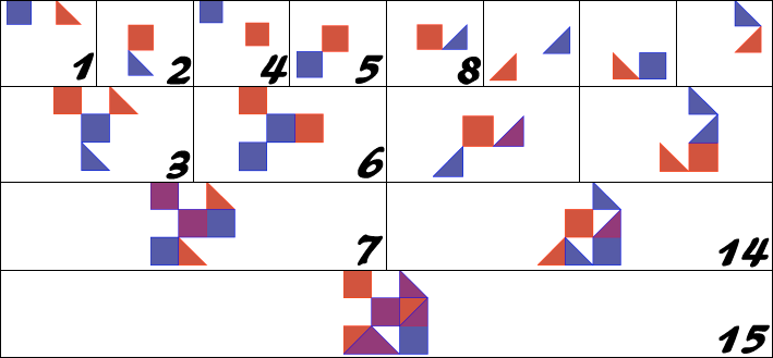
In this figure, a field of 3x3 is used and intersections are done up to level 3.

The test and recursive structure and sequence can be compared to a genealogical Ahnentafel, the unions to marriages, the number 15 to the proband, having two parents, four grandparents, eight great-grandparents, et cetera.

Checking results

While we can run the program and see the results (the program optionally creates an SVG file), we have to have a mechanism to check if the results are correct.

Luckily we are doing geometry, we are doing mathematics, we are doing set theory, so we can use that to check our results.

Checks are done in each step, so during the processing of two polygons. Besides a union (u), an intersection (i) is done. The area is calculated of the original polygons (p and q), of the union, and of the intersection. And it always must be that the area of the union equals to the area of both input polygons, minus the area of the intersection. So: A(u) == A(p) + A(q) - A(i). A simple check, all done by the library itself.

So we can run the check for thousands of times, and for various levels, field sizes, boxes and triangles. It now also runs for counter clockwise polygons and open polygons.

It is not the case that it was without errors the first time... There have been many errors, especially in the self-tangencies, points were two polygons in a multi-polygon touch each other. That all have been solved. So running this test was absolutely valuable.

Seven levels

After seven levels in a field of 10x10 we might get the next results:

i2c

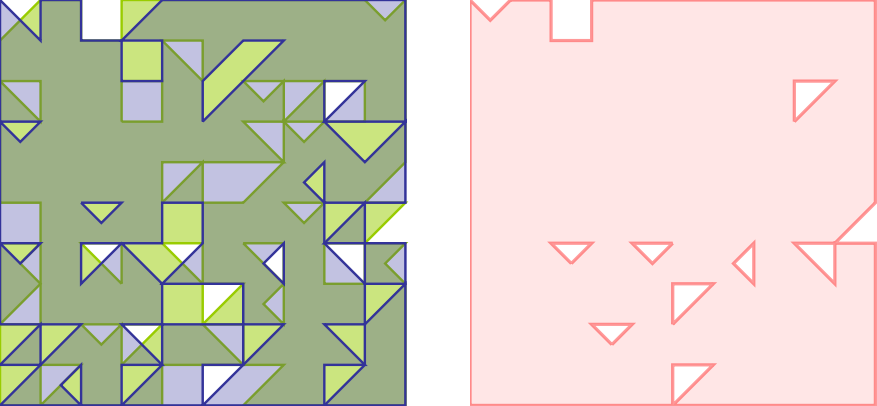
At the left the two input polygons (green and blue), at the right the union in red. After these seven levels in the 10x10 field, the unions are that large that they nearly completely fill up the whole area.

Last month I did most tests in this configuration, 10x10 and up to 7 levels. 7 levels results in 255 tests, this is 28-1

Twelve levels

Twelve levels results in 212-1 unions and shows in a 100x100 field like this:
1c

and we can go further and further, but for Boost.Geometry the tests do not give problems anymore. It all runs fine. This test (so 8191 unions and intersections ending in this complexity) runs in two seconds on my current machine (actually, to be precise, it is doing the union twice because the overlay function is reused in other tests as well).

Unit test

It is a sort of a unit test, because the program checks itself. I also use it as a unit test. But note that the program is based on random input, and that a 30-level test resuls in 230-1 unions and intersections (~1G). So it runs for a while, and including this in the standard Boost test suite will not be appreciated. So this recursive_polygons can be run manually, and there are parameters to specify the number of levels, et cetera.

By the way, there are many real unit tests within Boost.Geometry, there are currently 118 source files using the (great!) Boost.Test library, and some of them use polygons which are created by this testprogram as their input.

Conclusion

This recursive polygon unit test has been very valuable and, besides that, such tests are nice to program. The whole program, links are given above, is rather short, and it is of course Open Source. This test might be useful for other libraries as well.

Sunday, December 19, 2010

Intersections (1)


Intersections (1)


The boolean operations are probably the most interesting parts of the Boost.Geometry library.

Boolean operations are, based on two polygons:
  • intersection, returning polygons containing areas present in both input polygons
  • union, returning polygons containing all areas present in either one of the input polygons
  • difference, returning polygons containing areas present in one of the input polygons, but not in the other
  • symmetric difference, returning polygons containing areas present in one of either input polygons, but not in both
In other words, boolean operations are spatial implementations of mathematical set theoretic operations. Based on two polygons A and B:
  • intersection: A and B, also written as A ∩ B
  • union: A or B, also written as A ∪ B
  • difference: A and not B, also written as A \ B
  • symmetric difference: A xor B, also written as A ∆ B
The difference operation (also known as relative complement) is the only operation of these which is not commutative, A \ B results in another geometry than B \ A. 

The basics

1a

This blog will not explain the whole algorithm, that would be way too long. Other of my future blogs or a future article will explain more details. The algorithm used in Boost.Geometry is an adapted version of the Weiler-Atherton algorithm. The basics are quite simple, and explained here, and also in adapted versions as from Greiner-Hormann. Note that I have adapted the algorithm myself, such that intersection points are not inserted in the originals but stored separately. Which is essential because we don't want to change the input polygons, and we neither want to copy the input polygons. I have made more adaptations, such that all situations including self-tangencies (in some articles called degenerations) and robustness are handled.

So only the very basics in this blog. There are two input polygons, A and B (here: green and blue), both oriented clockwise. The arrows indicate orientation at the starting points. Intersection points (orange) are calculated. During the calculation of the intersection points, traversal information is gathered: for an intersection (usually: go to the right), would it continue following the green or the blue outline... For example, at point 0, above, it is figured out that for an intersection the green line should be followed, and for a union the blue line. Both until the next intersection point is encountered. That requires sorting which is used heavily within the algorithm.

Turning right for intersections or left for unions is also visualized below, from an older part of the GGL-doc:

1f

How traversal information is figured out, and how intersection points are sorted, will be explained in another blog, maybe much later.

So intersection points and turn information are basically all that is necessary up to this point. The traverse function uses this information, and adds points to the accumulated output polygon. Added points can be either intersection points or original vertices. The output intersection then looks like this (slightly shifted by hand to show it better):

1c

Note that it can become (often much) more complicated, holes, intersections at vertices, self-tangencies, polygons-within-holes, multi-polygons, etc. 

Here the process for the intersection of a polygon with a polygon with two holes:
qg

Note that the numbers of the intersection points are shown in the order found, and not in the order of traversal. It is not possible to indicate intersection points with an order of traversal, because that order differs for intersection and union (check this in the picture above). The (manually added) red arrows depict the traversal for intersection, starting with the red "0".

Note also that holes are not a big addition to the algorithm, if they are oriented counterclockwise in clockwise polygons (and vice versa). This is an assumption that is made within Boost.Geometry. If this is the case, traversal can take its routes always in the same way. The union operation would create two holes, which are different from the original holes and stored automatically in the correct orientation.

All boolean algorithms are the same

I mean to say here: intersection, union, and (symmetric) difference are all the same.

We have seen above that for intersection and union the same information is gathered. Only one variable, the traversal-direction, determines what is the output. So easy, we have one algorithm in which we calculate intersection or union.

Now for the difference, it turns out that if we reverse one of the polygons (e.g. green one), such that it is oriented counter-clockwise, the difference is calculated automatically by calculating the intersection of that reversed A and the still normal B. That is not that strange, because it follows from a mathematical rule. The difference of A and B is the same as the intersection of the complement of A with B. And the complement of A (Ac) is just its reverse. Voila, we do another function with the same algorithm.

The complement (from older GGL-doc) of polygon A is the whole world but A.
1e

The symmetric difference, A xor B, is just adding the two differences: it is also defined as A and not B unioned by B and not A.

Concluding this: all operations intersection, union, difference and symmetric difference are calculated with this one algorithm. The algorithm consists of several sub algorithms, relevant for all operations, and I hope to describe them later in more detail.

Reversing

How do we take the reverse in the algorithm? In the past, I cheated and reversed the polygon before doing the algorithm. That was easy, but has two drawbacks: 1) the input must be copyable and 2) it takes time to reverse. So we don't do this anymore. We just iterate through it in reverse way. That is easy enough, using an iterator walking reversely though the vertices. Or, in the case of Boost.Geometry, we use a reversible_range, as explained in previous blog. It is all implemented using specializations and meta-programming.

The difference is shown below. On the left side the result, again shifted slightly to make things more clear. The right side shows the same but in a different way: the intersection of the complement of A (green) with B (blue).

1b2

The one algorithm handles all geometries

We have seen above that one algorithm is enough and that we can walk in reverse through the polygons to support differences. What if we have counterclockwise polygons? The answer is the same, we walk through it using our reversible ranges, which are in fact Boost.Range reverse_range adaptors. So we calk backwards through it during getting intersection points, and later when vertices are necessary for the output, and actually everywhere where it is used.

So we can handle clockwise and counterclockwise input polygons, and we can even handle one clockwise, one counterclockwise, and the output can also be clockwise or counterclockwise at wish. That last feature is done by appending points during traversal to the back of the output rings, or inserting them at the front.

The algorithm also handles combinations of rectangles and polygons, because a rectangle can be seen as a polygon. The only difference is that the calculation of intersection points is done more efficient. Furthermore, multi-polygons can be handled. Note that the intersection of two polygons can result in a multi-polygon.

So this seems a litany of what the algorithm can handle, and it does not stop here. Because Boost.Geometry algorithms are independant on their input point types, and also independant on their input polygon types, and other geometry types, the algorithm can handle any geometry type based on any point type. So it can handle 4-byte-floats but also 8-byte-doubles or high-precision types like TTMath. It can handle boost::geometry polygons but also ESRI polygons, provided those polygons are adapted to Boost.Geometry.

Another aspect of this algorithm is that it is coordinate system agnostic. It can handle cartesian polygons, but can also calculate intersections of spherical polygons. This is possible because the algorithm is based on sub-algorithms as calculating the intersection points, and finding the side (left/right) of a point with respect to two other points. If those algorithms are provided (currently they are not...) the intersection algorithm will handle them.

The fastest...

Finally, the implementation of boolean operations in Boost.Geometry is also the most efficient intersection algorithm which can be found. If people don't believe this, or want to test it, or help benchmarking: there are Open Source benchmarks. Other people are more independant as I am, help would be welcome.

Below intersection of two multi-polygons with self-tangencies, intersection is again shifted slightly. This comes from one of the robustness tests.

1d

Final remarks

Using the reversible_range for (symmetric) difference instead of reversing geometries, in the implementaiton,  was done yesterday. So all this stuff above was planned but, until yesterday, not implemented like it is today. So another step forwards is made.

The review report (from now more than a year ago) said:

Boolean operations: while the library provides a set of Boolean operations those seem to be not complete and/or robust in terms of clockwise/counterclockwise geometries, closed/open polygons. Robust Boolean operations are a strong requirement, so this should be fixed as reported by at least one reviewer.

This point is now dealt with. There are still a few tweaks to be done but they will disappear coming weeks. I didn't discuss robustness in this blog, and open polygons neither, but these issues are already addressed too.

Don't think you can implement boolean operations easily, though the basic algorithm is quite simple... There are about 100 cases for extraction of turn information from two intersecting segments. Besides that there are also dozens of cases necessary for self-tangencies, in GIS not so ubiquitous, but in games certainly important. I started the algorithm in January 2008 and rewrote it two times after that, one time before the review, and another time after it because there were issues with the implementation, self-tangencies, and robustness. Now it should be ready for production.

The implementation is heavily based on C++, generic programming, templates, specialization and meta-programming. I don't think it is easily translatable into another language (but D). Also in C#, where specializations (at runtime) are possible according to one of my previous blogs, metaprogramming is not possible, it is a compile-time mechanism.