Friday, June 24, 2011

Spherical Side Formula


Spherical Side Formula


This blog describes an algorithm and a formula to determine the side of one point relative to a segment (two other points), all three points located on a sphere.

The side informarmation is necessary for Boost.Geometry. It is used, among others, in the within algorithm, to check if a point is inside a polygon (point in polygon). With the spherical version of side, it can be checked if a point on a sphere (the earth) is inside a spherical polygon (e.g. a polygon measured in latitude, longitude).

It is also known as orientation (see also here and here)

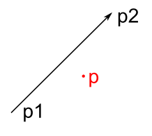
The Cartesian side is shown below. Point p is on the right side of segment p1-p2:
cs

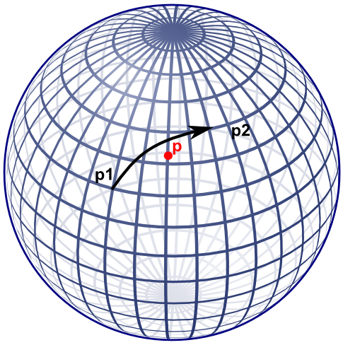
A visualization of ths spherical side is shown below, also here, point p is right of segment p1-p2.
ss

Note that if the cartesian side formula would be used on lat-long coordinates, this specific point would result on the left side.

Former approach

Boost.Geometry's former approach for spherical side used the useful aviation formulae of Williams, listed here. That did work but I was not completely satisfied about it:
  • it takes two * (3 cos, 3 sin, 1 atan) for the course, and then another 2 sin, and 1 asin, so in total 17 goniometric functions
  • it is non defined at the poles
  • I don't understand it fully, it seemed to me that there should be an easier way
An obvious alternative is translate to 3D cartesian coordinates and why not? After working this out a bit, it appeared that it indeed requires less goniometric functions. These goniometric functions are less performant and less precise, so if they can be avoided, the better. Also the new approach is also relatively easy, from mathematical perspective.

New approach

The new approach also uses sin and cos, but  less: for each of the points: 2 sin and 2 cos, in total 12 goniometric functions. Less then the former 17. More important, by design of Boost.Geometry, these might be precalculated such that for a spherical polygon it is not necessary to recalculate this again and again.

Besides that, the algorithm is easier to follow.

The algorithm

Let us calculate a plane through the two points of the segment, and the center of the sphere. This is the plane also containing the Great Circle. Let us then calculate at which side of the plane the point is located, either left of the plane, or right of the plane, or on the plane itself. The side with respect to the plane is also the side of the point with respect to the segment on the sphere.

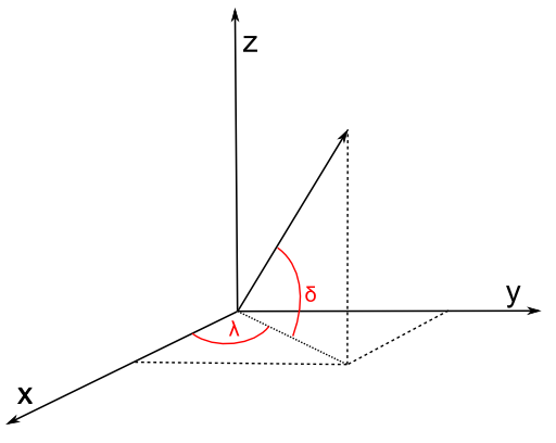
To calculate a plane, all three points are transformed from spherical coordinates (longitude, latitude) to cartesian coordinates (x, y, z). Described a.o. here with clear images. We can use the unit sphere, it is not necessary to take the radius of the Earth (or another sphere or sphere-like object) into account. Amsterdam, for example, then lies somewhere here: (0.614161755 0.042946374 0.788010754).


Converting can conveniently be done using Boost.Geometry's transform algorithm (if p1 is stored in cs::spherical_equatorial):

        typedef model::point<coordinate_type, 3, cs::cartesian> point3d;
        point3d c1, c2, c3;
        transform(p1, c1);
        transform(p2, c2);
        transform(p, c3);
coordinate system

Then we define a plane through the center of the Earth (0,0,0) and the two points. We use the generalized plane equation for that (a x + b y + c z + d = 0), described e.g. here. This is done by taking the cross product of the two vectors (a vector is here: a mathematical vector). These two vectors are normally called v and w. Because we use (0,0,0) the points are the vectors, we don't have to subtract anything to create a vector. So v is equivalent to c1, w is equivalent to c2.

The cross product is the normal vector, called n, normal to the plane, so perpendicular to the great circle of the two points. So we can take the cross product:

vector_type const n = geometry::cross_product(v, w);

We now have our generalized plane equation. To make that explicit, we can use the conventional symbols a, b, c:

        coordinate_type const a = get<0>(n);
        coordinate_type const b = get<1>(n);
        coordinate_type const c = get<2>(n);

For the generalized plane equation, we should calculate d by subsituting one of the points going through the plane. Let us take (0,0,0)! By taking 0,0,0, all terms a x, b y, c z will be zero, so d is zero. Therefore we don't have to calculate d.

        double const d = 0;

The generalized plane equation has the property that, if you substitute another point, it is either on the plane (then the result = 0), or at one side of the plane (then the result is positive), or at another side of the plane (then the result is negative). Just like the Cartesian side, described above. And that is exactly what we need:

distance_measure = a * get<0>(c3) + b * get<1>(c3) + c * get<2>(c3) + d;

and we have the result:

int side
            = distance_measure > 0 ? 1 // left
            : distance_measure < 0 ? -1 // right
            : 0;

Spherical Side Formula

We used convenient vector calculation here, making it a mathematical exercise. Of course we could write them all out and get a lot of goniometric functions back.

One big note here: geographers (as I am) always refer to coordinates on a sphere by defining 0 at the equator. But mathematicians define 0 at the upper pole of a sphere. Watch out, it is different. This blog assumes the geographic convention, so assumes a spherical equatorial coordinate system.

Let's present it as mathematic formulae (thanks to mathcast):


The first formula converts to x,y,z. Be sure to enter all angles in radians. Also, be sure that λ is longitude (and comes first in Boost.Geometry) and δ is latitude (there are many conventions for this but I'm using them from here, and not from here and here and here). Latitude is 0 at the equator, 90 at the North Pole (again: mathematicians use 0 at the North Pole, 90 at the aquator; that is known as the spherical (polar) coordinate system, we now refer to the spherical equatorial coordinate system).

The second formula is the cross product and defines the terms of the generalized plane equation. The third formula calculates the distance measure (dm). Because (2) and (3) do not have repetitive clauses, they could be combined into (4) and then, if wished, again, with the conversion, into (5).

The sixth pseudo-formula then defines the result, it is an interpretation of the distance measure dm.

Ellipsoidal Earth

The Earth is not spherical but approximates an ellipsoid, it is flattened at the poles. But the described spherical side formula works well on Earth. Let me try to prove that (note: I'm a geographer, not a mathematician).

A location defined by (λδ) essentially means a vector, either on a sphere, or on an ellipsoid. These vectors always have the same direction, so the same on a sphere as on an ellipsoid. Their lengths differ (on an ellipsoid they are often shorter) but the length of a vector does not influence the plane it encompasses. Therefore the plane formed by two locations and the center of the Earth is exactly the same plane as it is using a perfect sphere.

So: two points (a segment), on a sphere or on an ellipsoid, define the same plane.

The same applies for the third point. It is also a vector, having a direction. That vector, either on a sphere or on an ellipsoid, is located at the same side of the plane.

Q.E.D.

Code

Because of the formulae above, I don't give (pseudo)code. It is quite easy. I created a small Excel sheet containing the formula is here. It contains this example (on this useful site): gcmap The formula is also in Boost.Geometry.

Summary

Using some high-school mathematics I presented an algorithm and a formula to calculate at which side a point is with resepect to a segment, on a sphere or on the Earth. Google did not find this for me. So I hope that it will be of some use for some people. At least, it is useful for Boost.Geometry

Wednesday, May 18, 2011

Debugger Visualizers


Debugger Visualizers


When debugging in Visual Studio, watching the contents of a variable can be of great help. But as soon as a variable is of a custom type, it might be inconvenient.

For example Boost.Geometry. You can examine the contents of a point or a polygon in the Debugger Watch Window. But the representation of a point type is cumbersome: "{...}". If you click that open, you will see m_values and a meaningless pointer. Still awkward. If you click that m_values open, you see it again, in the Values column the same pointer again. Still no coordinates. If you click that pointer open, yes, you finally see the values! But it takes three steps (clicks).

dv1

If you examine a polygon, you have to do these three steps for each point in each of its rings!

You will be tired of that soon, especially if you know it can be helped using the Visual Studio Debugger Visualizers. It seems this method is not documented by Microsoft, so it is a bit of hacking, but descriptions can be found on the web (references below).

This is the recipe how to do it:
  • go to the folder "c:\Program Files (x86)\Microsoft Visual Studio 10.0\Common7\Packages\Debugger" (usually there, path may change, this path is for VS 2010)
  • make a backup of the file autoexp.dat because we are going to change it
  • open autoexp.dat in an editor (it is (on Windows 7) convenient to edit in another path, because saving requires Administrator rights)
  • go to the bottom, just before [hresult]
  • enter the cryptic lines shown below this bullet list
  • save the file (if you did edit it in another path, copy it back, giving Administrator rights)
These are the lines to add:
boost::geometry::model::d2::point_xy<*,*>{
   preview ( #("(x=", $e.m_values[0], " ,y=", $e.m_values[1], ")") )
}
It is a bit abstruse. In preview ( #( ) ) you have to enter member variables of your class (which should be called $e for enigmatic reasons). You can mix them up with strings. All is comma separated. Note that the parentheses should be placed as displayed.

After this exercise, restart Visual Studio and debug again and... you will see a much better appearance of our point in the Watch window:

dv2
We don't have to click at all. Our point is just there, x- and y- coordinates specified. Oh yes, 4.56 is now 4.55999 but that is something different, it has to do with floating point precision. We ignore that in this blog.

Definition for Boost.Geometry

At this moment I have point_xy but also model::point defined. I could have more but this is already very useful. Linestrings or polygons automatically use these point presentations, and because std::vectors are visualized by Microsoft (in that same file autoexp.dat), it is all very clear in the Watch Window.

So the section I defined looks like this:

; BOOST.GEOMETRY

boost::geometry::model::point<*,2,*>{
   preview ( #("(", $e.m_values[0], " , ", $e.m_values[1], ")") )
}

boost::geometry::model::point<*,3,*>{
   preview ( #("(", $e.m_values[0], " , ", $e.m_values[1], " , ", $e.m_values[2], ")") )
}

boost::geometry::model::d2::point_xy<*,*>{
   preview ( #("(x=", $e.m_values[0], " ,y=", $e.m_values[1], ")") )
}
I have it running in Visual Studio C++ 2010 Express, and also in Visual Studio C++ 2005 Express. Debugging visualizers is a bit tricky, if you make an error you might get an exception window. But in version 2010 it is better than it was in version 2005.

References

There is more than this. More is explained on these pages: And in .NET (but this is actually another solution, implementing a custom visualizer in code):


Friday, May 6, 2011

SqlGeometry and Boxes


SqlGeometry and Boxes


I wanted to write a blog about partitioning (calling an algorithm using an on-the-fly quadtree or octree) and how it is implemented in Boost.Geometry, and how it could also be used / implemented for the SqlGeometry type. But somehow that blog will be too large and I blog here just about a box/rectangle in SqlGeometry. It is not too difficult, but I just googled and did not find other blogs saying the same things, so I hope it adds something.

STEnvelope


The OGC/ISO STEnvelope function, supported by spatial databases and many geometry libraries, returns the envelope of a geometry. An envelope is: a bounding box or bounding rectangle, also known as an axis aligned bounding box (aabb), a bbox, a minimum bounding rectangle (mbr) or an extent.

More in detail, STEnvelope returns a Geometry object describing a rectangle. OGC does not know the notion of a box. That is sometimes a bit inconvenient, but it is how it is. Boost.Geometry created a Box Concept, because Boost.Geometry is strongly typed, and envelopes returning polygons with always four or five points would confuse the non-OGC users of our library.

I blogged earlier about the spatial extent of a query in SQL Server, here.

A box is a simple geometry, with (in 2D) a minimum x and y and a maximum x and y. But how to get that from a geometry in a spatial database... I mean, the envelope returns a polygon containing five points (assuming it is closed), is the first point lower left? And is that guaranteed? The OGC specifications say: The minimum bounding box for this Geometry, returned as a Geometry. The polygon is defined by the corner points of the bounding box [(MINX, MINY), (MAXX, MINY), (MAXX, MAXY), (MINX, MAXY), (MINX, MINY)]. So yes, it should be guaranteed.

Let's look at it in more detail.

SQL Server


In SQL Server it indeed seems the case that the first point of the polygon returned by STEnvelope is the lower left point. Then, the third point must be the upper right point. Because, if you consider the polygon clockwise, it is the third point, and if it is counterclockwise, it is also the third point.

We use this query:

select geometry::STGeomFromText('POLYGON((0 0,2 5,4 1,0 0))',0).STEnvelope().STPointN(3).STAsText()

... to get the third point (which should be upper right), and it indeed gives me: POINT(4 5)

PostGIS


In PostGIS, the first point of the polygon returned by ST_Envelope is the lower left point as well. Great.

As you (maybe) know, SQLGeometry uses methods, PostGIS uses functions. So the corresponding nested function calls would be:

select ST_AsText(ST_PointN((ST_Envelope(ST_GeomFromText('POLYGON((0 0,2 5,4 1,0 0))',0))), 3))

But... no result, we get a null value back. Looking at the OGC specs, this is correct: NumPoints is defined for a LineString and not for a Polygon. SqlServer is somewhat more relaxed here (as is Boost.Geometry), returning the total number of points of a polygon (including interior rings, if any).

OK, behaviour is correct, so we try again, now inserting the ST_Boundary function (making a linestring of the boundary of a polygon). Our new function call is:

select ST_AsText(ST_PointN(ST_Boundary((ST_Envelope(ST_GeomFromText('POLYGON((0 0,2 5,4 1,0 0))',0)))), 3))

... and we have our upper right point. Using a 1 for the last value (the index of ST_PointN is one-based) would return the lower left point.

Boost.Geometry


Boost.Geometry, as said, returns a box (conforming a Box Concept) for the envelope (or assigns one). So this is more or less outside the discussion... Having a box you can get the minimum-corner coordinates (might be 2D, might be 3D, or more) and the maximum-corner coordinates.

SqlGeometry


I blogged about the useful SqlGeometry type here. The SqlGeometry type is polymorphic, it can be any OGC geometry. But, therefore, it cannot be a Rectangle (because, remember, a rectangle is not an OGC Geometry). So if it contains a Rectangle, it is a Polygon.

Using C#, it would be useful to get the coordinates from a Polygon returned by STEnvelope and that goes like this. Note that (in the light of defensive programming) we don't even assume that the first point is the lower left point. We add this code as a function (we could add it to a class GeometryExtensions, but for now we don't). It is called BoxToCoordinates, see the code below.

And, for symmetry, and because it is convenient, or often necessary (last reason most important ;-) ) we add a counterpart function as well, which creates a rectangle for you given four coordinate values. We call that one CoordinatesToBox, see code below.


The code


OK, this was some preparation for next blog, not too difficult, and now we can convert an STEnvelope result to coordinate values, and back. The full code is displayed below. Between BoxToCoordinates and CoordinatesToBox, there will be some more interesting calculations in the next blog. Stay tuned.

using System;
using Microsoft.SqlServer.Types;

namespace BlogSqlGeometryBox
{
    class Program
    {
        public static SqlGeometry FromWkt(string text, int srid)
        {
           return SqlGeometry.STGeomFromText(new System.Data.SqlTypes.SqlChars(text), srid);
        }

        public static SqlGeometry CoordinatesToBox(double x1, double y1, double x2, double y2, int srid)
        {
           SqlGeometryBuilder builder = new SqlGeometryBuilder();
           builder.SetSrid(srid);
           builder.BeginGeometry(OpenGisGeometryType.Polygon);
           builder.BeginFigure(x1, y1);
           builder.AddLine(x1, y2);
           builder.AddLine(x2, y2);
           builder.AddLine(x2, y1);
           builder.AddLine(x1, y1); // Yes, we close it neatly
           builder.EndFigure();
           builder.EndGeometry();
           return builder.ConstructedGeometry;
        }

        private static void MakeFirstSmaller<T>(ref T a, ref T b) where T : IComparable
        {
           if (a.CompareTo(b) > 0)
           {
               // Exchange the two values
               T t = a;
               a = b;
               b = t;
           }
        }

        public static void BoxToCoordinates(SqlGeometry box, out double x1, out double y1, out double x2, out double y2)
        {
           SqlGeometry lower_left = box.STPointN(1);
           SqlGeometry upper_right = box.STPointN(3);
           x1 = lower_left.STX.Value;
           y1 = lower_left.STY.Value;
           x2 = upper_right.STX.Value;
           y2 = upper_right.STY.Value;

           
// Defensive programming:
           MakeFirstSmaller(ref x1, ref x2);
           MakeFirstSmaller(ref y1, ref y2);
        }

        static void Main(string[] args)
        {
           SqlGeometry triangle = FromWkt("POLYGON((0 0,2 5,4 1,0 0))", 0);
           SqlGeometry box = triangle.STEnvelope();

           double x1, y1, x2, y2;
           BoxToCoordinates(box, out x1, out y1, out x2, out y2);

           // Do something with these coordinates. Let's create a larger box
           x1 -= 1;
           y1 -= 1;
           x2 += 1;
           y2 += 1;

           box = CoordinatesToBox(x1, y1, x2, y2, 0);

           System.Console.WriteLine(box.STAsText().ToSqlString().ToString());
        }
    }
}

Writing:

POLYGON ((-1 -1, -1 6, 5 6, 5 -1, -1 -1))

Friday, April 29, 2011

SqlGeometry types and LINQ

SqlGeometry types and LINQ


Last year I started to use the Microsoft .NET SqlGeometry types and I like them very much. Thanks to Bert Temme who attended us (at Geodan) on their existance. See also this page with an introduction.

In short, the SqlGeometry is the type used for the SQL Server Spatial geometry objects. But it can also be used outside of SQL Server environments: it is contained in a pure .NET assembly. The download page says: "This component can be installed separately from the server to allow client applications to use these types outside of the server."

So the SqlGeometry type is comparable to other Geometry libraries, such as Boost.Geometry, GEOS and NTS (the JTS for .NET).

SqlGeometry functionality follows the OGC/ISO specifications quite closely. This means there is not much more than OGC functionality. Sometimes there is the wish to do other things than that. For example: select only the polygons from a geometry collection. Or: select only the polygons larger than X square meters from a MultiPolygon. There comes LINQ into place.

Installing the assemblies to use SqlGeometry

To use SQLGeometry, you need to have a reference to Microsoft.SqlServer.Types, which can be found in C:\Program Files\Microsoft SQL Server\100\SDK\Assemblies (on my (64 bit) machine in c:\Program Files (x86)\..., indicating 32 bits). If not there, download it from here (there is a 64 bits version there).
Note that you have to add the reference manually, by browsing on the file system, it does not appear in the reference tab (at least not on my system, using Microsoft Visual C# 2010 Express).

After that, just add:
using Microsoft.SqlServer.Types;

The geometry collection

A geometry collection is one geometry consisting of several sub-geometries, which possibly can have different types (e.g. linestrings and polygons).

A geometry collection is sometimes not convenient. For example: MapServer cannot display them. And there are probably more GIS packages which do not display geometry collections, because most mapping software is based on layers, and most layers are defined either on a layer with points (or multi-points), or a layer with lines (or multi-linestrings), or on a layer with polygons (or multi-polygons), but in most cases not on a layer with polygons and lines, and in even more cases not on a layer with geometry collections.

Geometry collections can come into existence during an intersection. If you overlay, for example, two valid polygons which share a part of their boundaries in opposite directions, that shared boundary will form a linestring, while the rest of the intersection (if any) will form a polygon. The polygon and the linestring form together a geometry collection. The next SQL statement generates a (probably unwanted) geometry collection:
select geometry::STGeomFromText('POLYGON((0 0,0 8,8 8,8 4,4 4,4 0,0 0))', 0) 
    .STIntersection(geometry::STGeomFromText('POLYGON((4 0,4 8,8 8,8 0,4 0))', 0))

The result is: GEOMETRYCOLLECTION (POLYGON ((4 4, 8 4, 8 8, 4 8, 4 4)), LINESTRING (4 4, 4 0))

Because geometry collections are often not displayed, functionality to remove all linestrings from a geometry collection would be very useful, or crucial. SqlGeometry does not offer this functionality, but it is possible to build it. It can be built by creating WKT's of all sub-geometries, and parsing and recombining them, but LINQ offers a more elegant way.

Selecting polygons from a geometry collection

We design our algorithm as:
  • create a list of geometries from the geometry collection
  • remove the linestrings and points from this list
  • build a Polygon or a MultiPolygon from the polygons kept in the list

Creating the list

Creating a list of geometries can be done using the STGeometryN and STNumGeometries functions, which are available. We can iterate through the single geometries and add them to the list, using:

var list = new List<SqlGeometry>(); 
for (int i = 1; i <= geometry.STNumGeometries().Value; i++)
{
    list.Add(geometry.STGeometryN(i));
}

Note that STGeometryN uses a one-based index, instead of the usual zero-based index.

Because we think this functionality is general, and will often be reused, we make an extension method of it (I really like them!). So we make a static class called GeometryExtensions and we add a static method containing the piece above, and we can just call:

IList<SqlGeometry> list = geom.ToList();

on any variable geom of type SqlGeometry. See source code below for the extension method.

Creating a geometry from a list

Of course, we want to have the reverse as well, making an SqlGeometry from a list of polygons. The key is that an STUnion is required to make a valid result. If two polygons of the list mutually overlap, this overlap will be resolved by STUnion. Even if there is no overlap, the STUnion has to be called because there is no STAdd function available. Alternatively we could make use of the SqlGeometryBuilder type which is available in the SqlGeometry library. However, using STUnion guarantees a valid result. The next loop does this for us:
SqlGeometry result = null; 
foreach (SqlGeometry g in list)
{
   result = result == null ? g : result.STUnion(g);
}

Using LINQ

So having programmed step 1 and step 3 as extension methods, and having a convenient list, we can now implement step 2 using LINQ:

var result = (from g in geom.ToList() where g.STGeometryType().ToString().ToLower() == "polygon" select g).ToSqlGeometry(); 
The magic. This one line statement with LINQ selects the polygons from an on-the-fly list, and put them via another list back into an SqlGeometry. In the listing below it is formatted as three lines.

The complete listing

using System; 
using System.Collections.Generic;
using System.Linq;

using Microsoft.SqlServer.Types;

namespace SqlGeometryBlog1
{
    public static class GeometryExtensions
    {
        // Converts a multi-geometry to a list of single-geometries
        public static List<SqlGeometry> ToList(this SqlGeometry geometry)
        {
          var list = new List<SqlGeometry>();
          for (int i = 1; i <= geometry.STNumGeometries().Value; i++)
          {
         
    list.Add(geometry.STGeometryN(i));
          }
          return list;
        }

        // Converts a list of geometries to a multi-geometry
        public static SqlGeometry ToSqlGeometry(this IEnumerable<SqlGeometry> list)
        {
          SqlGeometry result = null;
          foreach (SqlGeometry g in list)
          {
         
    result = result == null ? g : result.STUnion(g);
          }
          return result;
        }

        // For convenience, we add two extra methods
        public static SqlGeometry FromWkt(string text, int srid)
        {
          return SqlGeometry.STGeomFromText(new System.Data.SqlTypes.SqlChars(text), srid);
        }
        public static String ToWkt(this SqlGeometry geometry)
        {
          return geometry.STAsText().ToSqlString().Value;
        }
    }

    class Program
    {
        static void Main(string[] args)
        {
          var geom1 = GeometryExtensions.FromWkt("POLYGON((0 0,0 8,8 8,8 4,4 4,4 0,0 0))", 0);
          var geom2 = GeometryExtensions.FromWkt("POLYGON((4 0,4 8,8 8,8 0,4 0))", 0);

          var geom = geom1.STIntersection(geom2);
          System.Console.WriteLine(geom.STIsValid().Value);
          System.Console.WriteLine(geom.ToWkt());

          var list = geom.ToList();
          var selection = from g in list where g.STGeometryType().ToString().ToLower() == "polygon" select g;
          geom = selection.ToSqlGeometry();
          System.Console.WriteLine(geom.ToWkt());
        }
    }
}

The output

True
GEOMETRYCOLLECTION (POLYGON ((4 4, 8 4, 8 8, 4 8, 4 4)), LINESTRING (4 4, 4 0))
POLYGON ((4 4, 8 4, 8 8, 4 8, 4 4))


Friday, April 8, 2011

Extent of a SQL Server Spatial table


Extent of a SQL Server Spatial table


PostGIS does have a convenient spatial aggregation function: ST_Extent. SQL Server Spatial does not have that functionality. This little blog shows how to achieve its effect.

PostGIS


Given a table (e.g. called world1) with a geometry column (e.g. called geom), a call to the PostGIS function ST_Extent will give a neat box containing all geometries. For example:

select ST_Extent(geom) from world1;

returns a bounding box:

BOX(-180 -89.9,180 83.674733)

SQL Server Spatial


SQL Server Spatial follows OGC closely and therefore does not implement this functionality. Neither it has implemented it as a so-called extended geometry method. I've seen various creative solutions on the web, e.g. here and here and here. Most of these efforts are based on iterating through the rows, which is possible but often inconvenient (because of the required loop) and (also therefore) probably less performant. I will not say that my solution is performing better, but at least it is one SQL statement.

Be prepared on use of with, my current favorite SQL clause.  I described it earlier here.

So what happens: we define a sort of on-the-fly view of all the envelopes (select geom.MakeValid().STEnvelope() as envelope from world1). (The call to MakeValid() is only necessary if there might be invalid geometries in the table). Then we ask for the corner points of that viewy thingy. An envelope is a rectangle, always containing five points, where the fifth point is closing point and therefore the same as the first point. So either point 1 and 3, or point 2 and 4 are the opposite corners of a rectangle. So we take point 1 and point 3 (as done in first creative solution I referenced above). We define a second on-the-fly view of this, using the first view as input. To get both diagonally opposite points, we union them (union all is required). Note that I'm referring to an SQL union here, not to a spatial union.

Those on-the-fly views can be (very conveniently) implemented using with. I name them then viewy but that's up to you. So envelope_viewy is the first one and corner_viewy is the second one.

The complete SQL statement is then, for a column called geom in a table called world:

with
  envelope_viewy as
  (
    select geom.MakeValid().STEnvelope() as envelope from world1
  ),
  corner_viewy as
  (
    select envelope.STPointN(1) as point from envelope_viewy
    union all select envelope.STPointN(3) from envelope_viewy
  )
select min(point.STX) as min_x,min(point.STY) as min_y,max(point.STX) as max_x,max(point.STY) as max_y
from corner_viewy

And voilà, you will get:
min_x    min_y    max_x    max_y
-180    -89.9    180    83.674733

The same! (Of course, I used the same table, world1, used from my shapefile research-still-to-be-finished).

You can also create a stored procedure of this (e.g. called ST_Extent).

PostGIS remark


Writing this blog, I noticed a strange thing of the PostGIS ST_Extent. It only works for 2D, there is explicitly written in the documentation that it does not work for 3D (use a ST_Extent3D for that). But it delivers a 3D box. And indeed it is explicitly typed as a 3D box. I wonder why.